Field Remedy: 2065
| Subject: |
Engine Z19DTH/ J - Intake manifold, swirl
flaps, actuator out of order, DTC: P1109, P2075 set |
| Models: |
Engines: |
Option: |
| Vectra-C 2004...,Signum 2004...,Zafira-B
2005...,Astra-H 2004... |
Z19DTH,Z19DTH,Z19DTH,Z19DTH| Z19DTJ |
|
| Complaint: |
Customer complaint about lack of power and
SVS lamp on. The following trouble codes might be set based on the
installed application: a.) EDC16 C9 (2-actuator strategy, i.e.
pressure sensor as well as pressure regulator fitted at fuel rail)
TECH 2 shows DTC: P1109. b.) EDC16 C39 (1-actuator strategy, i.e.
only pressure sensor fitted at fuel rail). TECH 2 shows DTC:
P2075. |
| Cause: |
Problem might be caused due to sticking
swirl flap or due to malfunction from swirl flap actuator. |
| Production: |
Several modifications introduced since SOP.
Latest improvement was a design change at the swirl flaps itself in
order to make the flaps more robust and to prevent them from
sticking. Engine-BP: Z19DTH17228334 (28.02.2007). |
Remedy:
In case of customer complaint perform TECH 2 swirl flap actuator test
in order to evaluate the problem.
Recommendation:
Remove upper beauty cover in order to see the swirl flap linkage
mechanism. Switch on ignition (no need to start the engine) take
TECH 2 out of the vehicle to the engine bay. Change into swirl flap
actuator test and perform test. If linkage does not move at all but
the actuator motor itself is working (audible) it might be that:
--->
>
>
 either the internal actuator motor mechanism is faulty
--->
>
>
 or the pin ball from the actuator lever has come off, the lever
is bent or has just slipped off from the actuator joint. In this case
the actuator needs to be replaced.
Note: If the modified intake manifold (=swirl flaps) is already
installed please replace only the actuator.
In any other case it might be that the swirl flap linkage got stuck
during the actuator test or does not move completely from one end to
another. If this happens the intake manifold needs replacement
together with actuator.
The procedure for replacement of the intake manifold has been changed
and will be published on TIS 2000 as soon as possible. In Advance the
new procedure is given below in this document.
Working Procedure:
Note:
It is not necessary to disassemble the toothed belt.
    Important:
    When working on the fuel system it is essential to pay attention
    to cleanliness as even the smallest dirt particles can lead to
    faults in engine operation or in the fuel system. Open fuel
    connections must be sealed with appropriate plugs from the Opel
    Parts Catalogue (catalogue number: 45 06 154 /
    part number: 9201697). Sealing plugs are only intended to be used
    once.
1. Open bonnet.
2. Disconnect battery
    - detach ground clamp
        – loosen nut
3. Only Zafira-B: Remove bulkhead lock part
    - see working procedure "Bulkhead Lock Part, Remove and Install",
      group "A", Service Instruction Zafira-B.
      (Document Number 01101113)
4. Raise vehicle completely.
5. Remove lower engine cover.
6. Place collecting container below vehicle.
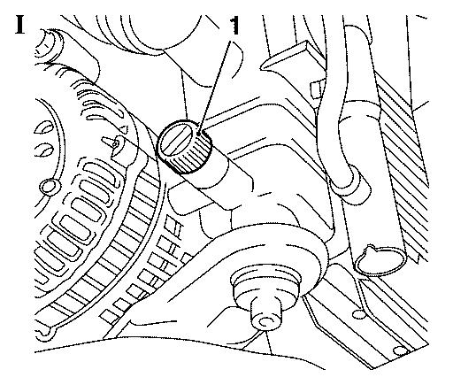
7. Drain coolant (Picture I)
    - open drain plug (1) at radiator
    - collect coolant
    - close drain plug
8. Lower vehicle completely.
9. Remove engine cover.
10. Remove air filter housing
    Astra-H:
    - see working procedure "Air Cleaner Housing, Remove and Install",
      group "J", Service Instruction Astra-H.
      (Document Number 00701767)
    Zafira-B:
    - see working procedure "Replacing the air cleaner housing",
      group "J", Service Instruction Zafira-B.
      (Document Number 01101348)
    Vectra-C:
    - see working procedure "Air Cleaner Housing, Remove and Install
      (Z 19 DTH)", group "J", Service Instruction Vectra-C.
      (Document Number 00602767)
11. Only Vectra-C: Remove right engine damper block
    - see working procedure "Right Engine Damping Block, Replace
      (Z 19 DTH)", group "J", Service Instruction Vectra-C.
      (Document Number 00602794)
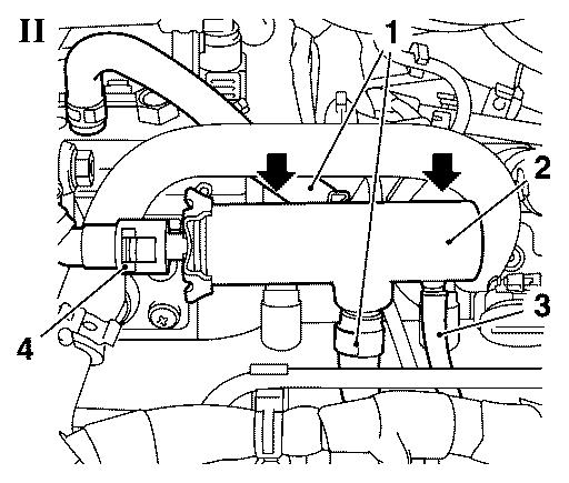
12. Detach fuel return damping case (2, Picture II)
    - remove fuel return line (4) with KM-796-A
    - remove 2x hose (1)
        - release 2 clamp
    - remove oil leak line (3)
    - unscrew 2x bolt (arrows)
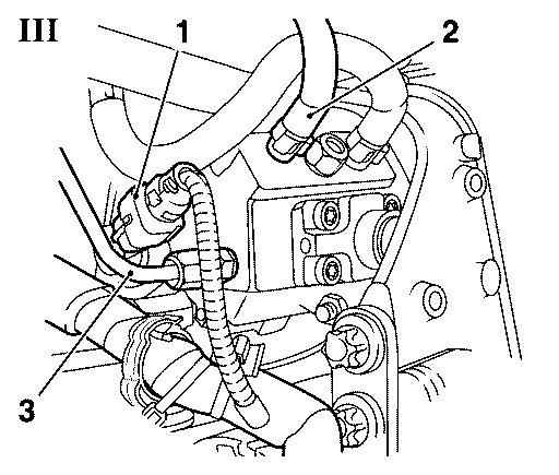
13. Bare high pressure pump (Picture III)
    Important:
    Close fuel connections of injectors and rail with closing caps
    from kit (catalogue number: 45 06 154 / part number: 9201697 )
    after removing pressure lines!
    - disconnect wiring harness connector high pressure pump (1)
    - remove high pressure line (3) high pressure pump to rail
        - loosen 2x lock nut
    Note:
    Close Rail, high pressure pump and high pressure line with closing
    caps from kit (catalogue number: 45 06 154 /
    part number: 9201697 ).
    - Remove fuel feed line (2) high pressure pump
        - Loosen clamp
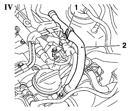
14. Detach engine vent hose (2, Picture IV)
    - release 2x clamp
    - unclip from bracket (1)
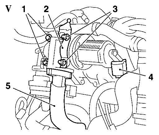
15. Remove EGR valve (Picture V)
    - remove metal tube EGR valve (5)
    - disconnect wiring harness plug (4)
    - unscrew 2x nut (3)
        - remove bracket (2)
    - unscrew 2x bolt (1)
    - unscrew 2x stud bolt
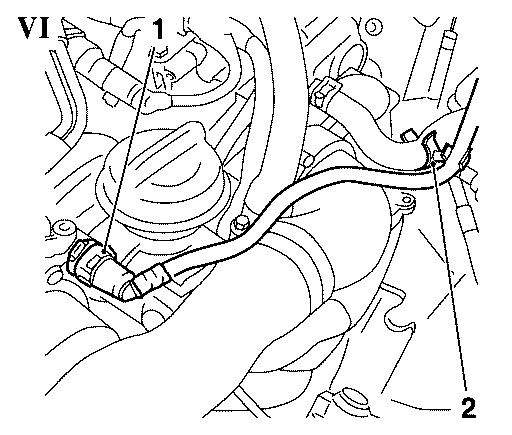
16. Remove brake servo vacuum line (Picture VI)
    - release quick-release fitting (1)
    - release clip (2)
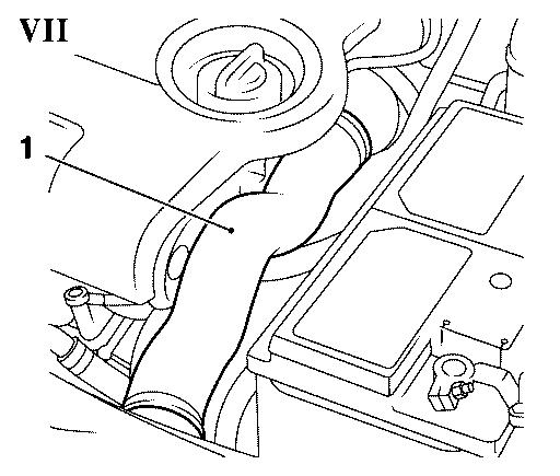
17. Remove charge air hose (1, Picture VII).
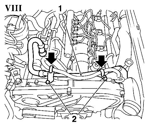
18. Remove engine ventilation line (1, Picture VIII)
    - remove engine ventilation hose
        – release quick fitting
    - remove 2x nut (2)
    - detach 2x wiring harness (arrows)
19. Only Vectra-C: Release coolant pipe
    - remove nut
    - release wiring harness
    - release 2x coolant hose
    - remove 2x screw
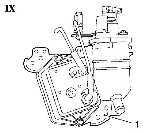
20. Remove oil separator/vacuum reservoir bracket (1, Picture IX)
    - loosen clamp
    - detach wiring harness
    - remove wiring harness
        – Detach 4x cable strap
        – Replace cable strap
    - unscrew 3 bolt
    - unscrew 2x nut
21. Detach engine management wiring harness (1, Picture X)
    - disconnect 10x wiring harness connector
        – Swirl valve actuator
        – Load pressure sensor
        – EGR valve
        – Coolant temperature sensor
        – Rail pressure sensor
        – Pressure regulator (not fitted since MY 07)
        – 4x sheathed glow plugs
    - unclip 4x bracket
    - lay wiring harness aside
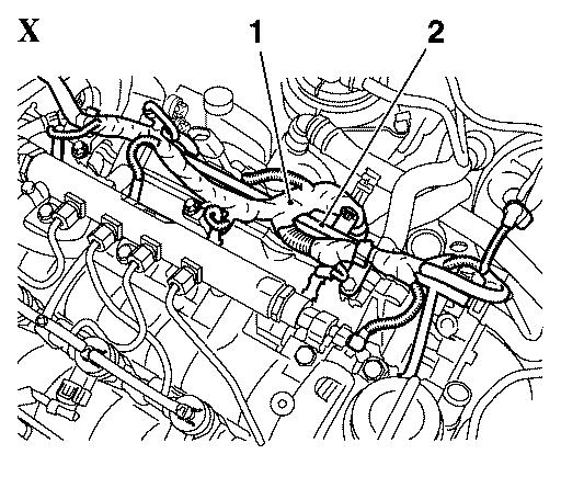
22. Detach coolant pipe (2) from intake manifold (Picture X)
    - detach 2x coolant hose from coolant pipe
        – release 2x clamp
    - remove coolant hose from coolant compensation tank
        – release clamp
    - remove 3x screw
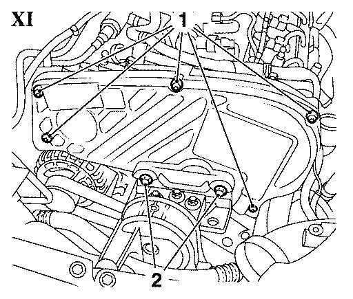
23. Remove upper toothed belt cover (Picture XI)
    - remove 5x bolt (1) with EN-47631
    - remove 2x bolt (2)
    - detach wiring harness
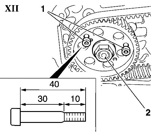
24. Adjust high pressure pump (Picture XII)
    Important:
    The retaining bolts need to have a length of 40 mm, the length of
    thread has to be 10 mm. Otherwise the sliding of the high pressure
    pump pulley on the retaining bolts can not be guaranteed!
    - turn steering wheel to right position
    - turn crankshaft in direction of engine rotation until retaining
      bolts (1) M 6x40 can be installed to bracket of high pressure
      pump
25. Loosen high pressure pump pulley (Picture XII)
- remove nut (2)
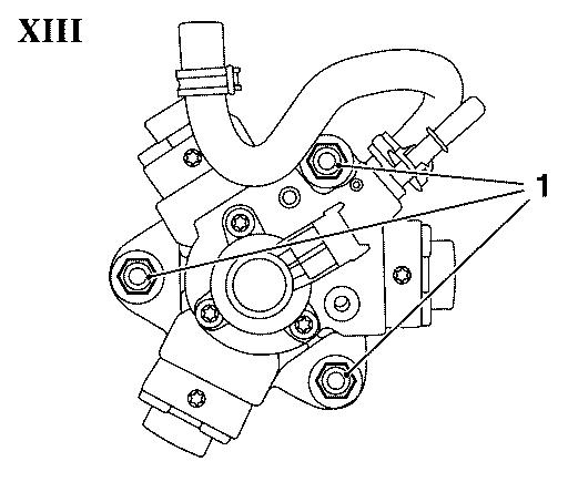
26. Loosen high pressure pump (Picture XIII)
- remove 3x nut (1)
    Note:
    Place rag below high pressure pump to avoid losing nut or woodruff
    key.
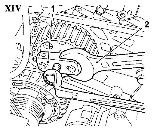
27. Remove high pressure pump (Picture XIV)
    Important:
    Assure that spindle of high pressure pump does not rotate!
    Important:
    Assure that woodruff key is removed!
    - push out high pressure pump completely in conjunction with
      EN-46790 (1), counterhold with flat wrench (2)
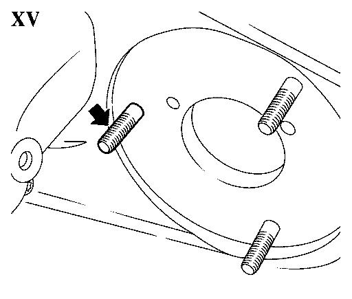
28. Remove stud bolt from bracket high pressure pump (arrow,
    Picture XV).
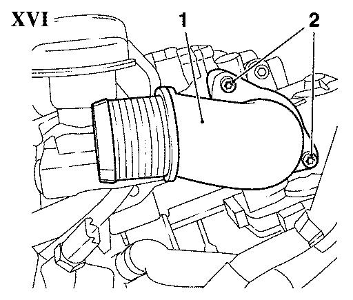
29. Remove inlet port (1) from throttle body housing (Picture XVI)
- remove 2x screw (2)
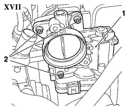
30. Remove throttle body housing (1, Picture XVII)
- remove 3x screw (2)
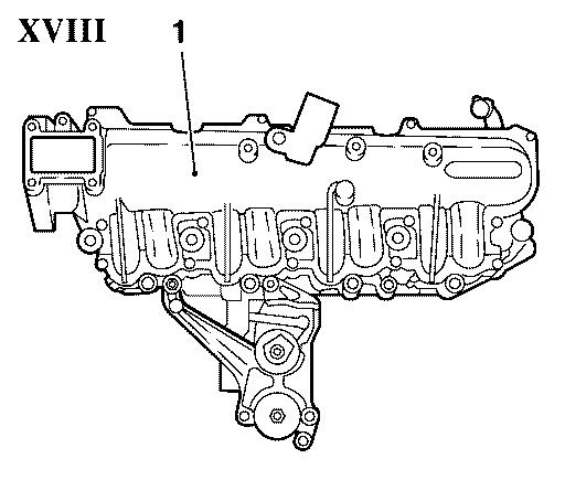
31. Remove intake manifold (1, Picture XVIII)
- unscrew 9x nuts
32. Remove attaching parts
    Note:
    When replacing the intake manifold, the swirl valve actuator must
    be replaced at the same time.
    - detach charge pressure sensor
        – unscrew bolt
    - detach swirl valve actuator
        – detach linking rod
        – remove 2x screw
    - remove connecting adapter coolant hose
33. Clean 2x thread
- coolant connection port
34. Fit attaching parts
    Note:
    When replacing the intake manifold, the swirl valve actuator must
    be replaced at the same time.
    - attach charge pressure sensor
        – tighten bolt
    - attach swirl valve actuator
        – tighten 2x screw
        – attach linking rod
    - install connecting adapter coolant hose
        – coat with sealant
35. Clean sealing surfaces.
36. Install intake manifold
- insert new gasket
    Note:
    Clip on 3x to intake manifold.
- tighten 9x new nut 25 Nm
37. Install throttle valve module
    - insert new gasket
    - tighten 3x bolts
38. Attach intake port to throttle valve module
- replace gasket
    Note:
    Coat with special grease (white).
- tighten 2x screw
39. Tighten stud bolt in high-pressure pump carrier
    Important:
    Don’t re-install woodruff key if old high pressure pump is
    re-used!
    Important:
    Assure that spindle of high pressure pump does not rotate!
40. Install high pressure pump
- tighten 3x new nut 25 Nm
41. Attach high pressure pump pulley
    Important:
    Push high pressure pump pulley onto spindle of high pressure pump
    by hand!
- tighten nut 50 Nm
    Note:
    Use new nut.
42. Remove retaining bolts from high pressure pump pulley.
    Important:
    Check high pressure pump pulley for sites of fracture and cracks!
43. Install upper toothed belt cover
    - tighten 5x screw using EN-47631
    - tighten 2x screw
    - attach wiring harness
44. Attach coolant pipe to inlet manifold
    - attach 2x coolant hose to coolant pipe
        – attach 2x clamp
    - attach coolant hose to coolant reservoir
        – attach clamp
    - tighten 3x screw 9 Nm
45. Attach engine management wiring harness
    - connect 10x wiring harness connector
        – swirl valve actuator
        – load pressure sensor
        – EGR valve
        – coolant temperature sensor
        – rail pressure sensor
        – pressure regulator (not fitted since MY 07)
        – 4x sheathed glow plugs
    - attach 4x
46. Install oil separator/vacuum reservoir bracket
    - replace 2x cable strap
    - tighten 3x screw
    - tighten 2x nut
    - attach engine venting hose
        – attach clamp
47. Only Vectra-C: Attach coolant pipe
    - tighten 2x screw
    - attach wiring harness
    - clip in 2x coolant hose
    - tighten nut
48. Attach wiring harness oil separator
    - attach wiring harness
    - attach 4x wiring harness with cable strap
        – replace 2x cable strap
49. Install engine venting pipe
    - attach engine venting hose
        – connect quick fitting
        Note:
        Catch must be audible.
    - tighten 2x nut
    - attach 2x wiring harness
50. Install air charging hose
- attach 2x clamp 3,5 Nm
51. Install vacuum line brake booster
- connect quick fitting
      Note:
      Catch must be audible.
- attach clip
52. Install EGR valve
- tighten 2x stud bolt
    Note:
    Insert 2x bolts with locking compound (red).
    - tighten 2x bolts
    - install EGR valve metal tube
    - connect wiring harness connector
    - tighten 2x nut
        – insert bracket
53. Attach engine venting hose
    - attach 2x clamp
    - attach to bracket
54. Attach new high pressure line to rail
    Important:
    Old high pressure lines may not be reused!
    - remove closing caps
    - tighten 2x lock nut
        – (M12) 25 Nm
        – (M14) 23 Nm
55. Connect wiring harness connector high pressure pump.
56. Attach fuel feed line high pressure pump
- attach clamp
57. Install fuel return damping housing
    - tighten 2x screw
    - attach fuel return line
        – connect quick fitting
          Note:
          Catch must be audible
    - attach fuel line
        – attach clamp
    - connect leak oil line
58. Only Vectra-C: Install right engine damper block
    - see working procedure "Right Engine Damping Block, Replace
      (Z 19 DTH)", group "J", Service Instruction Vectra-C.
      (Document Number 00602794)
59. Install air filter housing
    Astra-H:
    - see working procedure "Air Cleaner Housing, Remove and Install",
      group "J", Service Instruction Astra-H.
      (Document Number 00701767)
    Zafira-B:
    - see working procedure "Replacing the air cleaner housing",
      group "J", Service Instruction Zafira-B.
      (Document Number 01101348)
    Vectra-C:
    - see working procedure "Air Cleaner Housing, Remove and Install
      (Z 19 DTH)", group "J", Service Instruction Vectra-C.
      (Document Number 00602767)
60. Install engine cover.
61. Raise vehicle completely.
62. Install water draining hose to air filter housing.
63. Install lower engine cover.
64. Lower vehicle completely.
65. Only Zafira-B: Install bulkhead lock part
    - see working procedure "Bulkhead Lock Part, Remove and Install",
      group "A", Service Instruction Zafira-B.
      (Document Number 01101113)
66. Connect battery
    - attach ground clamp
        – tighten nut
67. Refill coolant.
68. Program volatile memories.
69. Close bonnet.
Spare-Parts: Part-No.: Catalogue-No.:
Inlet manifold                          55210201       58 50 180
Gasket, inlet manifold                  93179058        8 49 528
Nut, high pressure pump to bracket      93178880       58 19 147
Connection bar                          93186274       58 50 540
Valve inlet manifold                    93185801       58 50 574
Special nut high pressure pump          93178824       56 36 948
Washer, high pressure pump              93178879       58 19 146
High pressure pipe                      93179046       58 20 435
Gasket EGR valve                        93181665       58 51 374
Gasket throttle valve body              93179061        8 25 512
Locking compound                        90542117       15 10 181
Labour Times: Hours:
Astra-H:
J471500 Replace inlet manifold 3.0
Zafira-B:
J471500 Replace inlet manifold 3.3
Vectra-C:
J471500 Replace inlet manifold 3.6
| FunctionalGroup: |
J - Engine |
| Complaint Group: |
17 - Poor Design |
| Trouble Code: |
P1109,P2279(11),P2075 |
|
