|
Electro-Hydraulic Supply Unit EHPS TRW Gen. II,
Replace (RHD, (LHD X 17 DTL, Z 16 YNG, Z 22 SE))
|
Note: With the
introduction of the second generation of electro-hydraulic power
steering, there is now only one supplier. This new version can be
diagnosed using Tech 2. Further information on the diagnosis of the
electro-hydraulic power steering using Tech 2 – see in the
corresponding Checking Procedure.
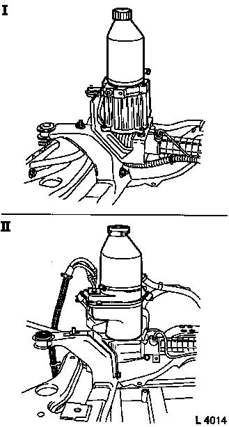
The round fluid reservoir of the EHPS Gen. II has a different
appearance to the fluid reservoir of the first generation (I) from
TRW in that it has a larger circumference and a bayonet catch
instead of the screw lock.
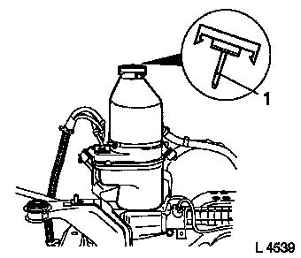
No filling level marks are provided on the fluid reservoir. The
dipstick (1) on the reservoir lid has a "MAX" filling level
mark.
|
|
 Remove Remove
|
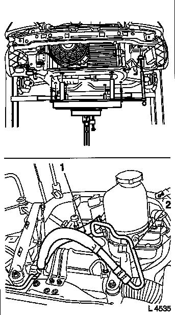
Remove front axle body – see operation "Front Axle Body,
Remove and Install" in group "E".
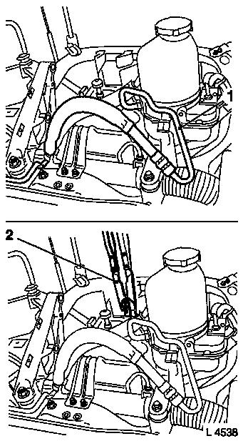
Remove return (1) and pressure line (2) from electro-hydraulic
supply unit – fluid escapes, place collecting basin
underneath.
|
|
|
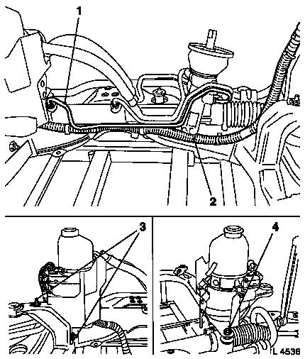
For vehicles with LHD: Remove front steering gear line (1) from
steering gear. Release steering wiring harness (2) from front axle
body – note cable routing.
Remove fastening nuts (3 and 4) from engine steering gear and
front axle body. Remove electro-hydraulic supply unit with bracket
and wiring harness. Remove steering from front axle body.
Note: When replacing
the electro-hydraulic supply unit, the heat shield must be
transferred, if necessary.
|
|
 Install
|
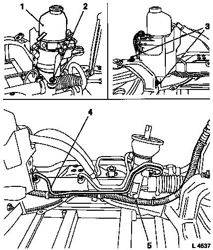
Position electro-hydraulic supply unit with bracket on steering
gear and front axle body – note steering wiring harness.
Attach bracket for electro-hydraulic supply unit (1) to front
axle body with fastening nuts (3) – tightening torque 22 Nm /
16 lbf. ft. Attach bracket for electro-hydraulic supply unit to
steering gear with fastening nut (2) – tightening torque 22
Nm / 16 lbf. ft.
For vehicles with LHD: Route steering wiring harness (5) and
attach to front axle body – ensure correct cable routing.
Attach front steering gear line (4) with new seal rings to steering
gear – tightening torque 30 Nm / 22 lbf. ft.
|
|
|
Attach pressure line (1) with new seal ring to electro-hydraulic
supply unit – tightening torque 30 Nm / 22 lbf. ft.
Attach return line to fluid reservoir with new retaining strap
and KM-J-22610 (2).
Remove cover from fluid reservoir. Remove fluid screen from
fluid reservoir and check for contamination; clean thoroughly if
necessary. Insert fluid screen into fluid reservoir.
|
|
|
Top up special fluid in fluid reservoir until "MAX" (1) mark on
the dipstick has been reached. Place lid on fluid reservoir and
seal off.
Install front axle body – see operation "Front Axle Body,
Remove and Install" in group "E".
|
|
|
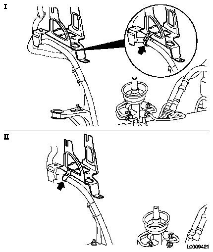
Note: In vehicles up
to MY 03, attachment of the steering wiring harness no longer takes
place on the front frame after replacement of the electro-hydraulic
supply unit, but with a cable tie to the ABS bracket (see
magnifying glass in Figure I). Figure II shows attachment of the
steering wiring harness in vehicles from MY 03.
|
|
Charge and bleed hydraulic system – see operation
"Hydraulic System, Charge and Bleed (EHPS Gen. II)".
|
