|
Repair an engine using a part-engine
 Remove Remove
| 1. |
Remove engine
| • |
For X 20 DTL, Y 20 DTL and Y 20 DTH up to MY 2003 
|
| • |
For Y 20 DTH as of MY 2003 and Y 22 DTR
|
|
| 2. |
Mount engine on engine assembly stands KM-412-A
|
| 3. |
Drain engine oil
| • |
Place collecting basin underneath
|
|
| 4. |
Remove charge air pipe
|
|
|
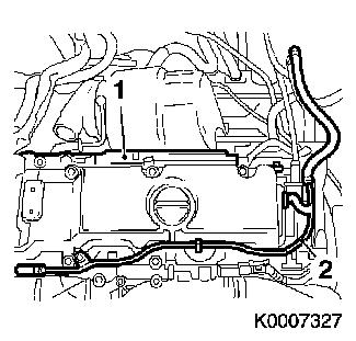
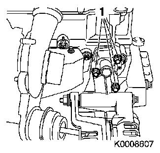
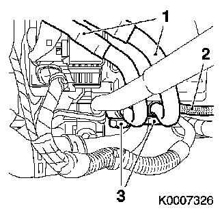
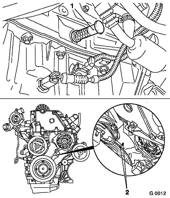
| 5. |
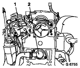
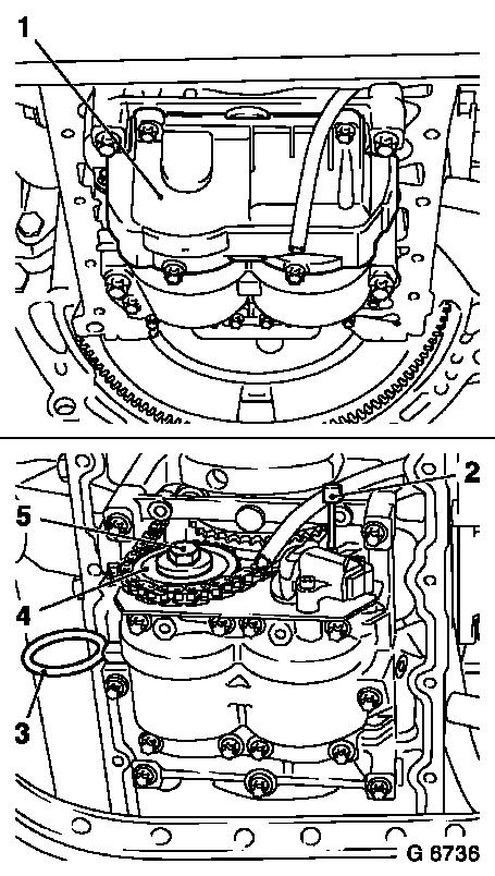
Unclip coolant hose (2)
| • |
Remove engine wiring harness bracket
|
|
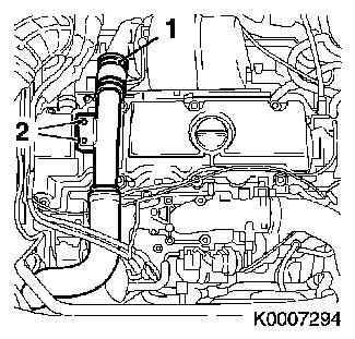
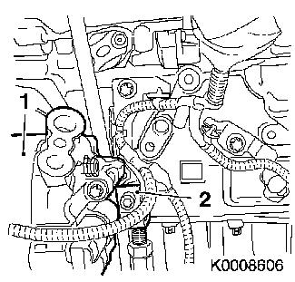
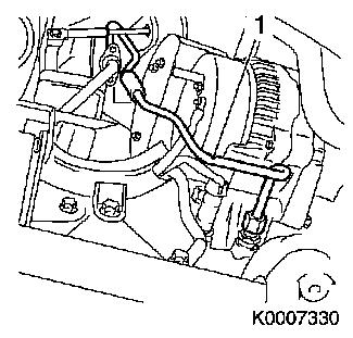
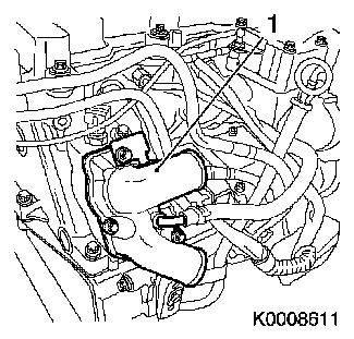
| 6. |
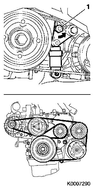
Detach wiring trough (1)
|
|
|
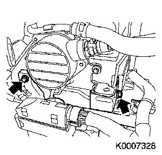
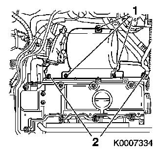
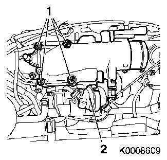
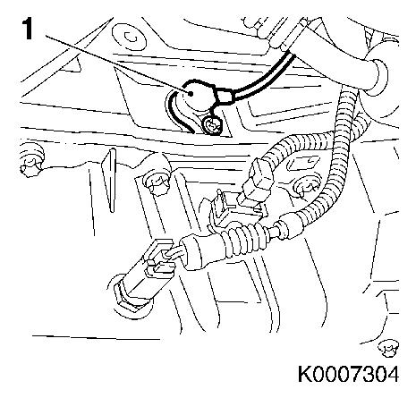
| 7. |
Remove engine wiring harness bracket
| • |
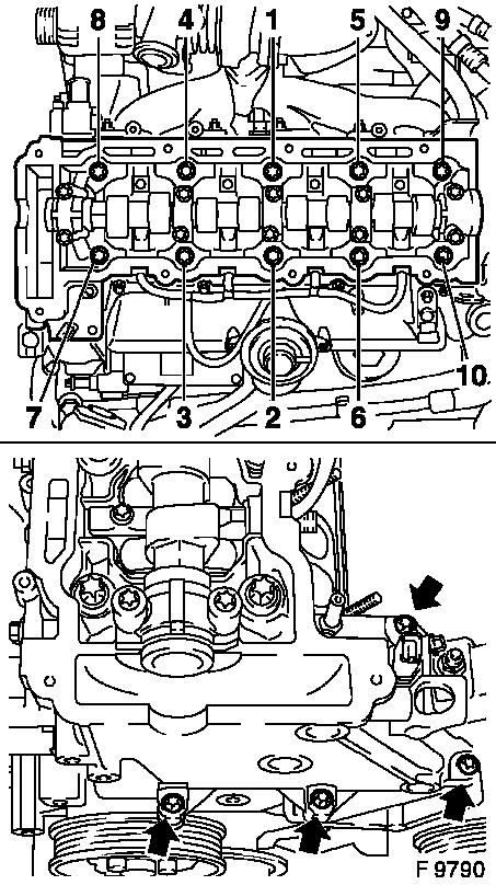
Remove 2 bolts (arrows)
|
|
|
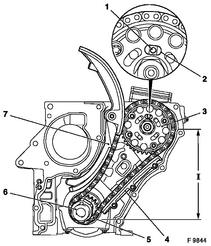
|
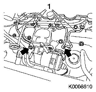
| 8. |
Remove engine wiring harness
| • |
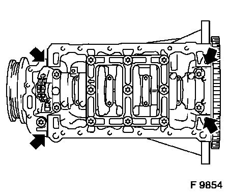
Remove 2 turbocharge control vacuum hoses
| – |
from vacuum reservoir, solenoid valve
|
|
| • |
Detach wiring harness plug for glow plugs (2)
|
Important: Close 2 engine control
unit connectors. Use KM-6154
|
| • |
Disconnect wiring harness plug
| – |
Oil pressure switch, intake pipe pressure sensor, crankshaft
pulse pickup, EGR valve, 2x engine control unit, coolant
temperature sensor, dynamic oil level control sensor, oil
temperature sensor, compressor
|
|
|
|
|
| 9. |
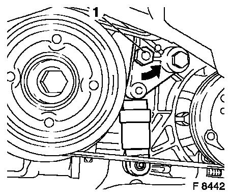
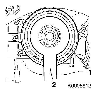
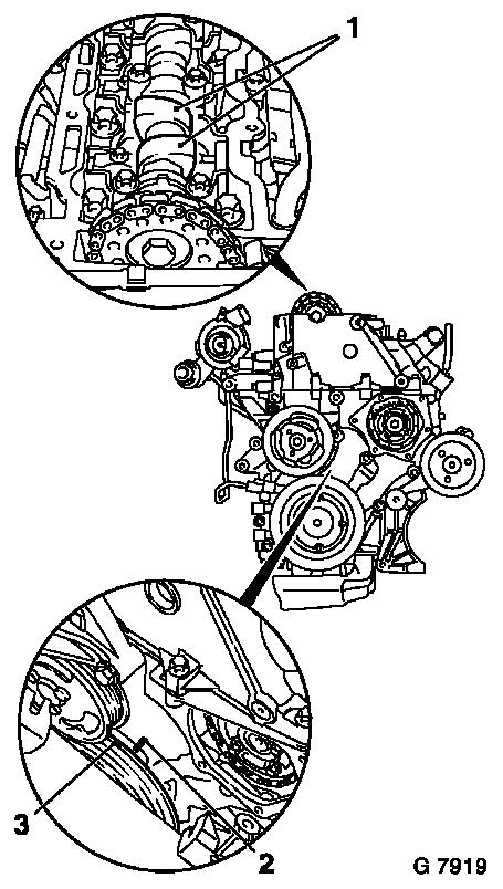
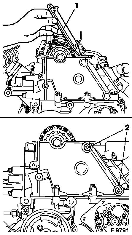
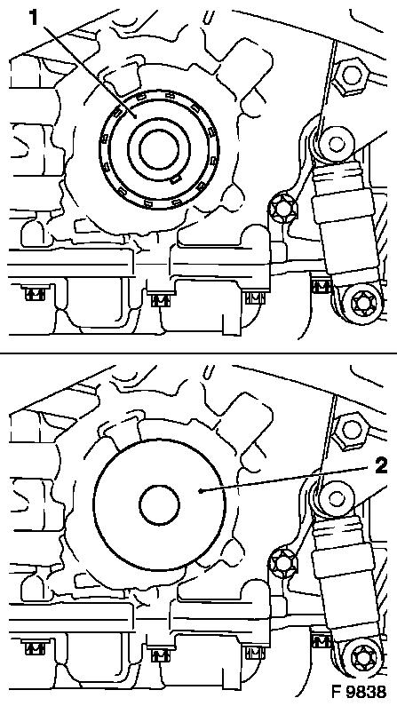
Detach ribbed V-belt
Note: Mark direction of
rotation
| • |
Tension ribbed V-belt tensioner at hex lug (1) anti-clockwise
(arrow)
|
|
|
|
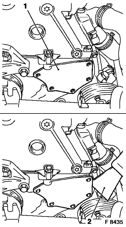
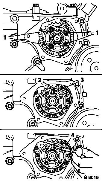
| 10. |
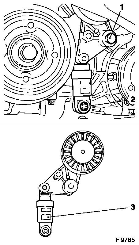
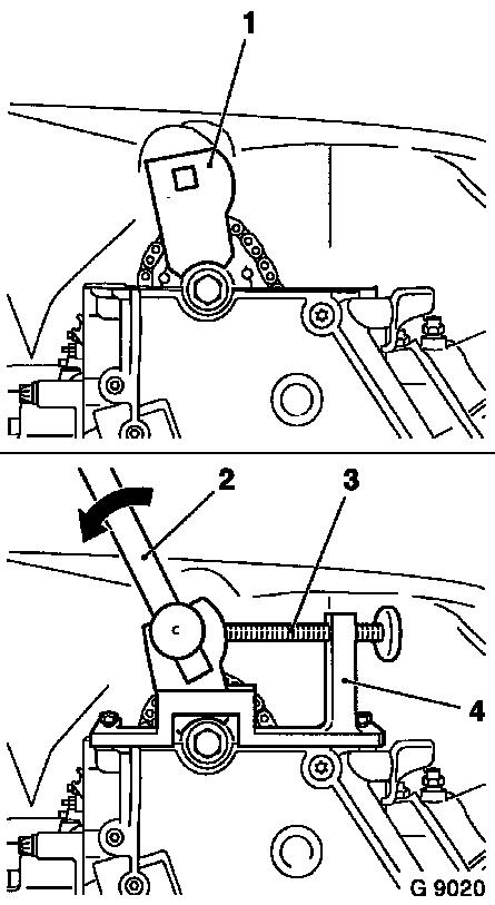
Remove ribbed V-belt tensioner
Important: Damper (3) may only be
stored in upright position. Incorrectly stored dampers may be bled
by repeated compression in installation position.
|
| • |
2 fastening bolts (1) and (2)
|
|
|
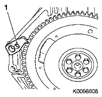
|
| 11. |
Remove alternator
| • |
Remove coolant hose bracket
|
|
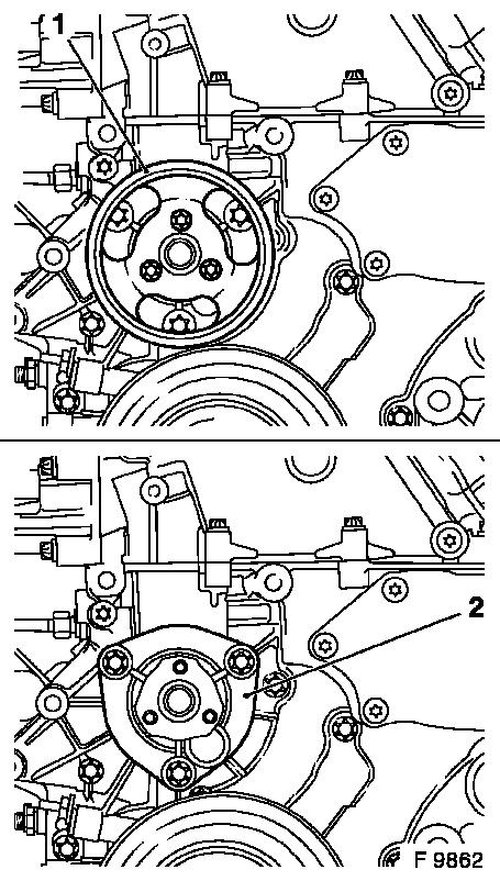
| 12. |
Remove compressor (1)
|
| 13. |
Remove compressor main bracket
|
|
|
| 14. |
Remove right engine bracket
|
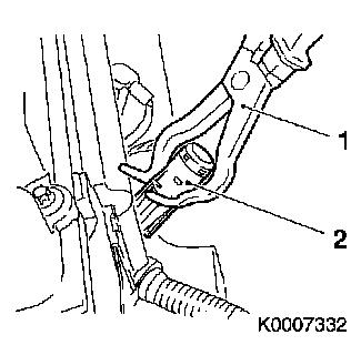
| 15. |
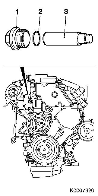
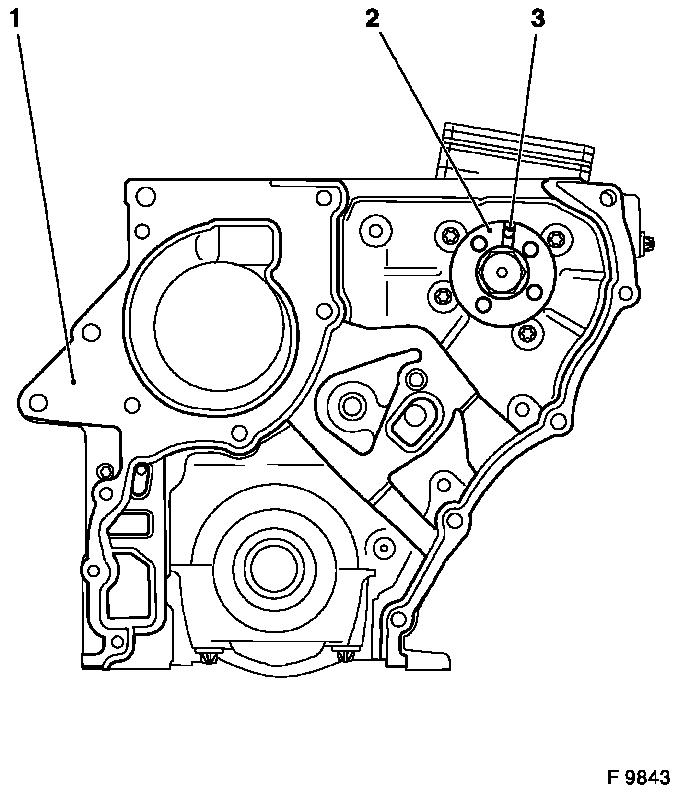
Remove timing case cover (1)
Important: Carefully separate
timing case cover from timing case using wide spatula (2) Do not
lever off timing case cover or use force to separate it from timing
case, as permanent deformation results in leakage.
|
| • |
6 fastening bolts
|
|
|
|
| 16. |
Remove turbocharger heat shield
|
| 17. |
Remove 2 exhaust manifold heat shields
| • |
2 fastening bolts (2)
Note: Carefully remove
right heat shield upwards
|
|
|
|
| 18. |
Detach turbocharger oil feed line (1)
| • |
Place collecting basin underneath
|
|
|
|
| 19. |
Remove exhaust manifold support
|
| 20. |
Detach turbocharger oil return line
| • |
From cylinder block connecting branch
|
|
| 22. |
Detach upper bracket for alternator (coolant flange)
|
|
|
| 23. |
Remove cylinder block coolant flange (2)
| • |
Detach coolant hose (1)
|
|
|
|
| 24. |
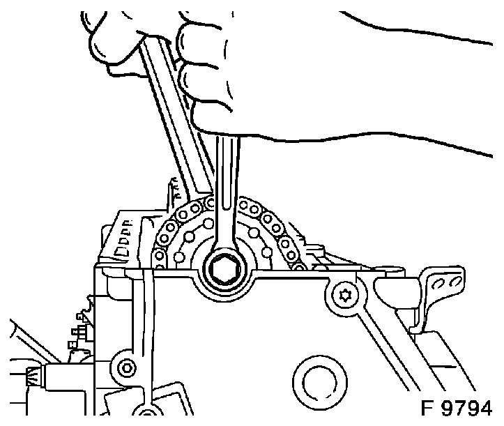
Loosen ribbed V-belt pulley crankshaft (1)
Note: Second installer
required
| • |
Loosen bolt
| – |
Up to MY 2003 and engine number 17K44148: Counterhold using
KM-977-1 (2) together with KM-956-1
|
| – |
From MY 2003 and engine number 17K44149: Counterhold using
KM-6619 (2) together with KM-956-1
|
|
|
|
|
| 25. |
Remove crankshaft ribbed V-belt pulley
|
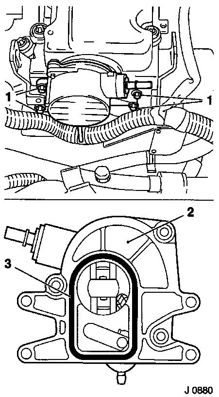
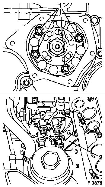
| 28. |
Remove throttle valve connecting piece
Note: For engines with
throttle valve vacuum unit (2): Detach vacuum hose
|
|
|
| 29. |
Remove injection line bracket
Note: Mark position of
the bracket
| • |
2 fastening bolts (arrows)
|
|
| 30. |
Remove injection lines (1)
| • |
Use KM-6098
Note: Note installation
position.
|
|
|
|
| 31. |
Detach thermostat housing (1)
|
|
|
| 32. |
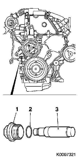
Remove oil dipstick tube
|
Important: Collect escaping
fuel
|
| 33. |
Remove 2 fuel lines (1)
| • |
Disconnect leak oil hose (2)
|
|
|
|
| 34. |
Detach vacuum line
| • |
From switchover valves vacuum unit
|
|
| 35. |
Remove vacuum pump (2)
|
|
|
| 36. |
Disconnect cylinder head cover.
|
| 37. |
Tighten oil drain bolt
| • |
Replace seal ring
| – |
Tightening torque 10 Nm / 7.5 lbf.
ft.
|
|
|
| 38. |
Remove crankshaft pulse pickup (1)
|
|
|
| 39. |
Attach crankshaft ribbed V-belt pulley bolt
|
| 40. |
Set engine to no.1 cylinder Ignition TDC
Note: Turn crankshaft
uniformly evenly in direction of engine rotation. Mark on torsional
vibration damper (3) must be positioned just before lug (2) on
timing case. Both cylinder 1 (1) cams must point upwards
|
|
|
| 41. |
Use KM-929 (1)
Note: Insert KM-929 into bore for crankshaft pulse pick-up.
Turn crankshaft uniformly in direction of engine rotation. KM-929 must latch in to the stop. Marks on
crankshaft ribbed V-belt pulley and lug on timing case must align
(2).
|
|
|
| 42. |
Use KM-927 (3)
Note: Arrow (1) on
Simplex injection pump gear must align with the recess in injection
pump flange and injection pump retaining bore (2). Insert KM-927 into injection pump retaining bore.
|
|
|
| 43. |
Use KM-932 (3)
Note: Place KM-932 on cylinder head. Pin (2) must engage in
camshaft bore (1).
|
|
|
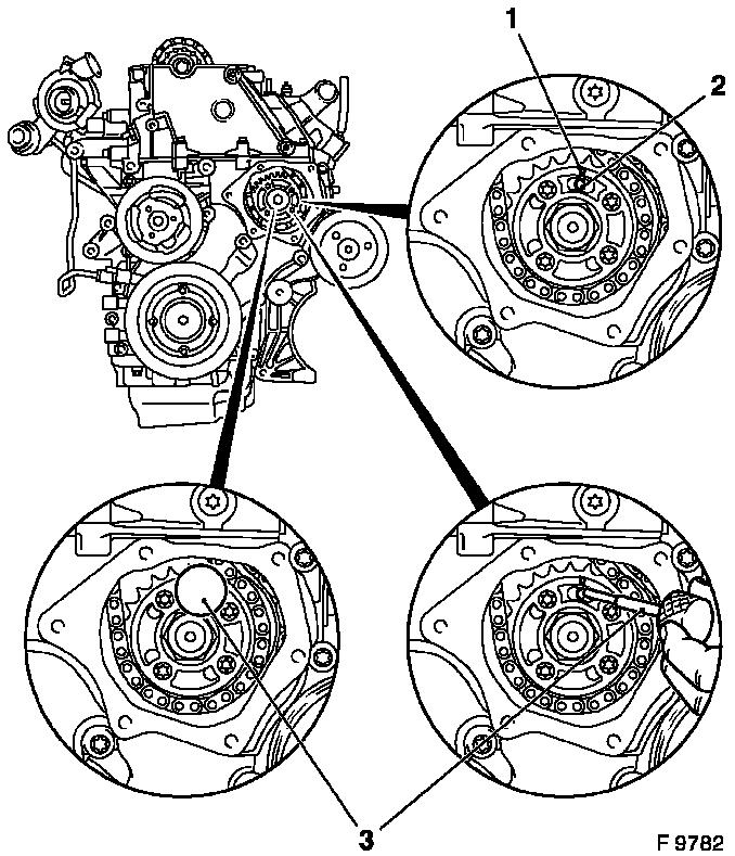
| 44. |
Remove Simplex chain tensioner (3)
Note: Note installation
position.
| • |
Remove bolt (1), seal ring (2), chain tensioner (3)
|
|
|
|
| 45. |
Remove guide rail for Simplex chain tensioner (1)
Important: Heat bolts intensively
with hot air blower and remove. Use suitable heat shielding
|
| • |
2 fastening bolts (2)
|
| • |
Remove guide rail upwards
Note: Note installation
position.
|
|
|
|
| 46. |
Remove KM-927 and KM-932
|
| 47. |
Remove camshaft sprocket
| • |
Remove 1 bolt
Note: Counterhold
camshaft at hexagonal section. Attach Simplex timing chain at a
suitable place.
|
|
|
|
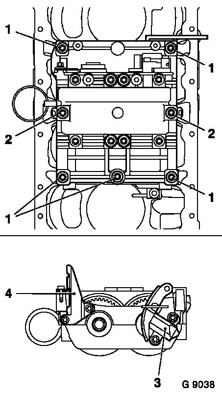
| 48. |
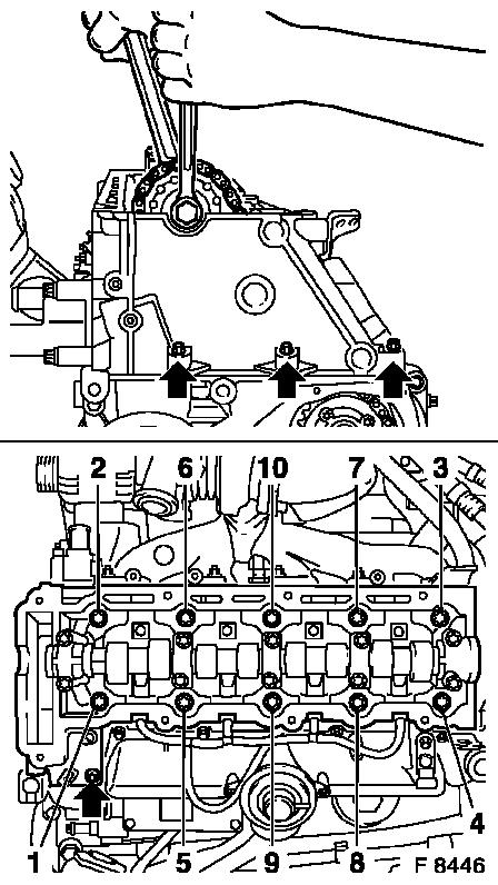
Loosen cylinder head
Important: Loosen cylinder head
bolts in illustrated sequence by first 1/4, then 1/2 turn
|
| • |
4 fastening bolts (M8) (arrows)
Note: Observe different
bolt lengths
|
| • |
10 fastening bolts (M12)
|
|
|
|
Important: Place cylinder head on
wooden blocks. Do not damage injectors, glow plugs or valves.
|
| 49. |
Remove cylinder head.
Note: 2nd mechanic is
required.
|
| 50. |
Remove cylinder head gasket
|
| 51. |
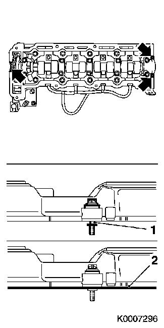
Remove Duplex chain tensioner (3)
Note: Note installation
position.
| • |
Remove bolt (1), seal ring (2), chain tensioner (3)
|
|
|
|
| 52. |
Remove Simplex injection pump gear
| • |
Lower Simplex timing chain downwards
|
| • |
Remove Simplex injection pump gear at side
|
| • |
Remove Simplex timing chain upwards
|
|
|
|
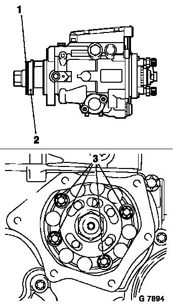
| 53. |
Release injection pump
| • |
Remove 4 fastening bolts (1)
|
|
| 54. |
Remove engine block coolant drain connection
| • |
Place collecting basin underneath
|
|
| 55. |
Remove injection pump
| • |
Remove cylinder block bolt
|
|
|
|
| 56. |
Remove coolant pump
| • |
Place collecting basin underneath
|
| • |
Ribbed V-belt pulley (1)
|
|
|
|
| 59. |
Detach balancer shaft unit cover (1)
|
| 60. |
Use KM-978 and KM-979
| • |
Set engine to no.1 cylinder Ignition TDC
|
| • |
Insert KM-979 (3)
Note: At side in
balancer shaft unit
|
| • |
Insert KM-978 (2)
Note: Push back chain
tensioner by hand. Insert KM-978 into
bores
|
|
|
|
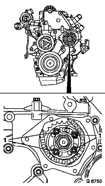
| 62. |
Detach balancer shaft unit
Important: Release bolts from
outside inwards
|
| • |
7 fastening bolts (1), (2)
Note: Guide rail (4)
and chain tensioner (3) must be transferred when replacing the
balancer shaft unit
|
|
|
|
| 64. |
Remove crankshaft ribbed V-belt pulley bolt
|
| 65. |
Remove timing case
| • |
13 fastening bolts
Note: Observe different
bolt lengths
|
|
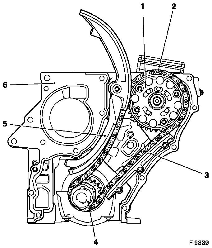
| 66. |
Detach slide rail (5)
|
| 67. |
Detach guide rail for Duplex timing chain (3)
|
| 68. |
Remove Duplex chain drive
| • |
Timing chain (2), crankshaft pulley (4), injection pump gear
(1)
|
|
| 69. |
Remove timing case gasket (6)
|
|
|
Important: Edge seal ring out of
timing case with suitable tool – ensure that the sealing
surfaces are not damaged
|
| 70. |
Remove crankshaft front seal ring, timing case seal ring
|
| 71. |
Remove cylinder block
| • |
Suspend engine on workshop crane.
|
| • |
Detach from KM-412-16 and KM-412-8-1
|
|
 Install
| 72. |
Attach cylinder block
| • |
Attach KM-412-16 and KM-412-8-1 to engine
|
|
| 73. |
Clean sealing surfaces
| • |
Timing case, cylinder block, cylinder head, oil pan
|
|
| 75. |
Clean thread.
| • |
2x simplex chain adjuster safety rails
|
| • |
6x clutch pressure plates
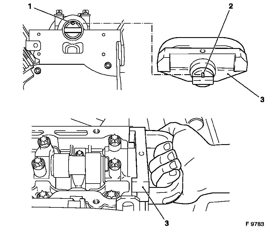
|
|
Important: A spacer washer (1)
may be installed on the injection pump flange (2) to adjust the
axial dimension. This spacer washer is allocated to the
corresponding fuel injection pump and must always be left on the
fuel injection pump flange. When installing a new fuel injection
pump, this is supplied with the axial dimension adjusted, i.e. with
or without spacer washer (1)
|
| 76. |
Insert injection pump.
|
| 77. |
Secure injection pump
| • |
4 fastening bolts (3)
| – |
Tightening torque 25 Nm / 18.5 lbf.
ft.
|
|
| • |
Attach injection pump bracket
| – |
Tightening torque 20 Nm / 15 lbf.
ft.
|
|
|
|
|
| 78. |
Attach engine block coolant drain connection
|
| 80. |
Use KM-929
| • |
Attach crankshaft ribbed V-belt pulley bolt
|
Important: Pull balancer shaft
unit chain upwards
|
| • |
Turn crankshaft to no.1 cylinder Ignition TDC
|
| • |
Remove crankshaft ribbed V-belt pulley bolt
|
|
| 82. |
Insert timing case gasket (1)
Important: Note guide sleeves.
Injection pump flange recess (2) must align with injection pump
retaining bore (3)
|
| • |
Replace gasket
|
|
|
|
Important: Ensure that recess is
positioned in injection pump flange and that injection pump
retaining bore (1) is centrally positioned in oblong hole (2) on
duplex injection pump gear – tension side (I) must be
taut.
|
| 83. |
Insert Duplex chain drive
Note: Check state of
crankshaft pulley spring washer, replace if necessary. Place
crankshaft pulley (6) with Duplex timing chain (5) and Duplex fuel
injection pump gear (3) on crankshaft or fuel injection pump
flange
|
| 84. |
Attach guide rail for Duplex timing chain (4)
| • |
3 fastening bolts
| – |
Tightening torque 8 Nm / 6 lbf.
ft.
|
|
|
| 85. |
Attach 2x tension rail (7)
| • |
1 fastening bolts
| – |
Tightening torque 20 Nm / 15 lbf.
ft.
|
|
|
|
|
| 86. |
Attach timing case.
| • |
13 fastening bolts
Note: Observe different
bolt lengths. Tighten bolts uniformly
| – |
Tightening torque 20 Nm / 15 lbf.
ft.
|
|
|
| 87. |
Install crankshaft front seal ring, timing case seal ring
| • |
Use KM-935-1 (1)
Note: Position seal
ring straight in timing case
|
| • |
Use KM-935-2 (2)
Note: Press in seal
ring until it lies flush in timing case. Use crankshaft ribbed
V-belt pulley bolt
|
|
|
|
| 89. |
Attach balancer shaft unit
Note: Guide rail (4)
and chain tensioner (3) must be transferred when replacing the
balancer shaft unit. Tighten bolts from inside outwards
| • |
2 fastening bolts (2)
| – |
Tightening torque 20 Nm / 15 lbf. ft. +
60°
|
|
| • |
5 fastening bolts (1)
| – |
Tightening torque 20 Nm / 15 lbf. ft. +
30°
|
|
|
|
|
| 90. |
Attach sprocket
| • |
1 new fastening bolt
| – |
Tightening torque 90 Nm / 66 lbf. ft. +
30°
|
|
|
| 91. |
Remove KM-978 and KM-979
|
| 92. |
Attach balancer shaft unit cover
| • |
4 fastening bolts
| – |
Tightening torque 8 Nm / 6 lbf.
ft.
|
|
|
| 93. |
Apply adhesive sealant
Note: Apply a bead of
adhesive sealing compound to joints (arrows) of timing case and
rear crankshaft bearing cap
|
|
|
| 94. |
Install oil pan
Important: Hand-tighten all
bolts
|
| • |
Replace gasket
|
| • |
To cylinder block, timing case
| – |
Tightening torque 20 Nm / 15 lbf.
ft.
|
|
|
Important: Clean thread in
crankshaft before attaching flywheel
|
| 96. |
Install flywheel
| • |
10 new fastening bolts
| – |
Tightening torque 45 Nm / 33 lbf. ft. +
30° + 15°
|
|
|
| 99. |
Fasten crankshaft ribbed V-belt pulley
|
| 100. |
Fasten ribbed V-belt pulley crankshaft
Note: 2nd mechanic is
required.
| • |
Tighten bolt 150 Nm + 45° +
15°
| – |
Up to MY 2003 and engine number 17K44148: Counterhold using
KM-977-1 together with KM-956-1
|
| – |
From MY 2003 and engine number 17K44149: Counterhold using
KM-6619 together with KM-956-1
|
|
|
| 101. |
Install coolant pump
Note: Replace
gasket
| • |
Coolant pump
| – |
Tightening torque 20 Nm / 15 lbf.
ft.
|
|
| • |
Ribbed V-belt pulley
| – |
Tightening torque 20 Nm / 15 lbf.
ft.
|
|
|
Important: Arrow (2) on simplex
injection pump sprocket must align with recess in injection pump
flange and lock bore (3) in injection pump.
|
| 102. |
Install Simplex injection pump gear
Note: Insert Simplex
timing chain with Simplex fuel injection pump gear and hand-tighten
Simplex fuel injection pump gear with fastening bolts (1). Ensure
bolt strength 10.9 of the fastening bolts
|
| 103. |
Tighten Simplex injection pump gear
| • |
4 fastening bolts (1)
| – |
Tightening torque 28 Nm / 20.6 lbf.
ft.
|
|
|
|
|
| 104. |
Install Duplex chain tensioner
Note: Note installation
position. Closed side of chain tensioner (3) must point to tension
rail
| • |
1 bolt (1)
| – |
Tightening torque 60 Nm / 44 lbf.
ft.
|
|
|
|
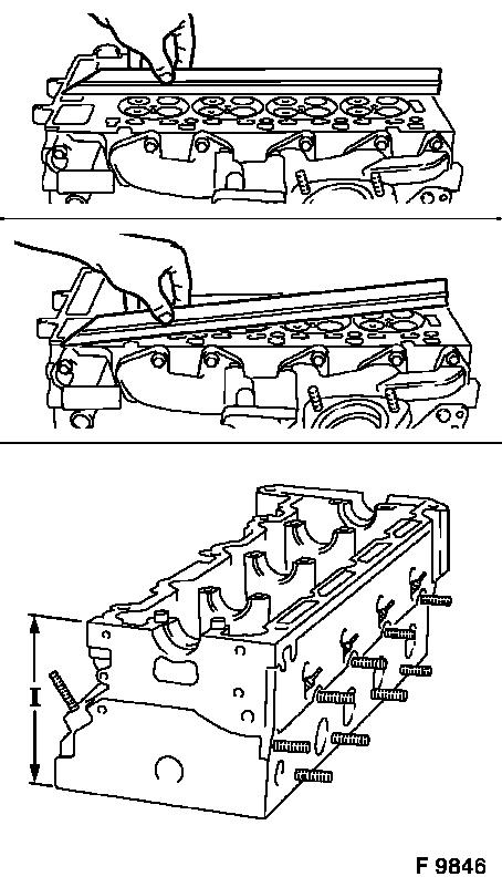
|
| 105. |
Check for plane surface
Note: Check sealing
surfaces in length and width for deformation and check for warping
along the diagonals
| • |
Cylinder head
Important: Resurfacing of the
cylinder head is not permitted.
|
| – |
With straightedge, feeler gauge
|
| – |
Measure cylinder head height
|
| – |
Sealing surface to sealing surface: Dimension (I) = 140 mm
|
|
|
|
|
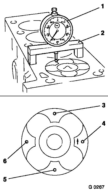
| 106. |
Measure piston projection
| • |
Insert MKM-571-B (1) into KM-301 (2)
|
| • |
Set dial to zero
| – |
Place probe on cylinder block
|
|
| • |
Measure piston projection at all four pistons
Note: Measure the
projection at two different points (3) and (4) or (5) and (6) for
each piston. To do this, place measuring bridge with the dial gauge
above the cleaned piston head on the cylinder block. Determine the
highest point by turning the crankshaft.
|
|
|
|
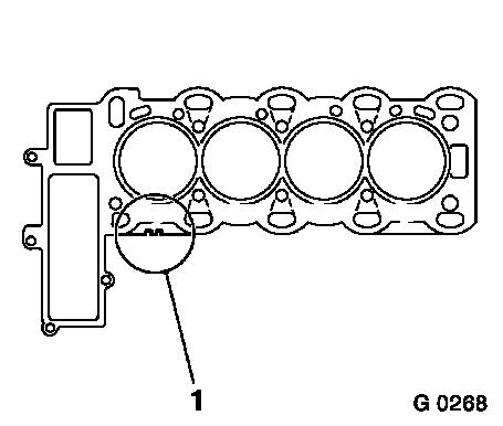
Important: The largest determined
piston projection is used for the selection of the cylinder head
gasket with corresponding identification. The identification
(notch) is located in position (1). Do not insert cylinder head
gasket with sealing compound.
|
| 107. |
Replace cylinder head gasket
| • |
Piston projection 0.51 – 0.60 mm
| – |
Thickness of gasket 1.3 mm
|
|
| • |
Piston projection 0.61 – 0.70 mm
| – |
Thickness of gasket 1.4 mm
|
|
| • |
Attach cylinder head gasket
|
|
|
|
| 108. |
Use KM-932 (3)
Note: Place KM-932 on cylinder head. Pin (2) must engage in
camshaft bore (1).
|
|
|
Important: Approx. 60° before
no.1 cylinder Ignition TDC
|
| 109. |
Turn crankshaft
|
| 110. |
Position cylinder head
Note: 2nd mechanic is
required. Note Simplex timing chain
|
| 111. |
Attach cylinder head
Note: Replace cylinder
head bolts
| • |
10 new cylinder head bolts
| – |
Tightening torque 25 Nm / 18.5 lbf. ft.
+ 65° + 65° + 65° + 65° + 15°
|
| – |
Use KM-470-B
Note: Note tightening
sequence.
|
|
| • |
4 new fastening bolts (arrows)
| – |
Tightening torque 20 Nm / 15 lbf. ft. +
30° + 5°
|
|
|
|
|
| 112. |
Set engine to no.1 cylinder Ignition TDC
Note: Turn crankshaft
uniformly evenly in direction of engine rotation. Mark on torsional
vibration damper (3) must be positioned just before lug (2) on
timing case. Both cylinder 1 (1) cams must point upwards
|
|
|
| 113. |
Use KM-929 (1)
Note: Insert KM-929 into bore for crankshaft pulse pick-up.
Turn crankshaft uniformly in direction of engine rotation. KM-929 must latch in to the stop. Marks on
crankshaft ribbed V-belt pulley and lug on timing case must align
(2).
|
|
|
| 114. |
Use KM-927 (3)
Note: Arrow (1) on
Simplex injection pump gear must align with the recess in injection
pump flange and injection pump retaining bore (2). Insert KM-927 into injection pump retaining bore.
|
|
|
| 115. |
Insert camshaft sprocket
| • |
Position Simplex timing chain
|
Important: Ensure that the
camshaft sprocket is not askew on the camshaft – camshaft
sprocket must lie plane on the camshaft.
|
| • |
1 new fastening bolt
|
|
| 116. |
Install guide rail for Simplex timing chain (1)
Important: Note installation
position of guide rail
|
| • |
2 new fastening bolts (2)
| – |
Tightening torque 8 Nm / 6 lbf.
ft.
|
|
|
|
|
| 117. |
Attach KM-933 (4)
| • |
Insert carrier (1)
Note: Position upright
in camshaft pulley
|
|
Important: It must be possible to
remove and install KM-927 under suction.
If this is not possible, the pressure on the adapter plate must be
slightly reduced using the adjustment screw (3).
|
| 118. |
Adjust KM-933 (4)
Note: Use handle (2) to
exert slight pressure on the carrier in the direction of arrow
(counter engine rotational direction) and fix in place with holder
bolt (3).
|
|
|
| 119. |
Secure camshaft sprocket
| • |
Tighten fastening bolt
| – |
Tightening torque 90 Nm / 66 lbf. ft. +
60° + 30°
|
|
|
| 120. |
Install Simplex chain tensioner (3)
Note: Note installation
position.
| • |
1 bolt (1)
| – |
Tightening torque 60 Nm / 44 lbf.
ft.
|
|
|
|
|
| 121. |
Remove KM-927 , KM-932 , KM-933 and KM-929
|
| 122. |
Turn crankshaft
Note: Turn crankshaft
slowly and uniformly two turns (720°) in direction of engine
rotation until just before no. 1 cylinder Ignition TDC. Mark on
crankshaft ribbed V-belt pulley (3) must be positioned just before
lug (2) on timing case. Both cylinder 1 (1) cams must point
upwards
|
|
|
| 123. |
Use KM-929 (1)
Note: Insert KM-929 into bore for crankshaft pulse pick-up.
Turn crankshaft uniformly in direction of engine rotation. KM-929 must latch in to the stop. Marks on
crankshaft ribbed V-belt pulley and lug on timing case must align
(2).
|
|
|
| 124. |
Use KM-927 (3)
Note: Arrow (1) on
Simplex injection pump gear must align with the recess in injection
pump flange and injection pump retaining bore (2). Insert KM-927 into injection pump retaining bore.
|
|
|
| 125. |
Use KM-932 (3)
Note: Place KM-932 on cylinder head. Pin (2) must engage in
camshaft bore (1).
|
|
|
| 126. |
Remove KM-932 , KM-927 and KM-929
|
| 127. |
Install crankshaft pulse pick-up
| • |
1 fastening bolt
| – |
Tightening torque 8 Nm / 6 lbf.
ft.
|
|
|
| 128. |
Attach cylinder head cover
| • |
Replace gasket
Note: Gasket (2) must
be inserted in gap (1) between cylinder head cover and sleeve.
Apply sealing compound to sealing surfaces (arrows)
|
| • |
8 fastening bolts
| – |
Tightening torque 8 Nm / 6 lbf.
ft.
|
|
|
|
|
| 129. |
Install vacuum pump
| • |
4 fastening bolts
| – |
Tightening torque 8 Nm / 6 lbf.
ft.
|
|
|
| 130. |
Attach vacuum line
| • |
To vacuum unit switchover valves
|
|
| 131. |
Install 2 fuel lines
| • |
2 banjo bolts
| – |
Tightening torque 25 Nm / 18.5 lbf.
ft.
|
|
|
| 132. |
Install oil dipstick guide tube
| • |
1 fastening bolt
| – |
Tightening torque 8 Nm / 6 lbf.
ft.
|
|
|
| 133. |
Attach thermostat housing
| • |
4 fastening bolts
| – |
Tightening torque 8 Nm / 6 lbf.
ft.
|
|
|
| 134. |
Install 4 injection lines
| • |
8 union nuts
Note: Note installation
position.
|
|
| 135. |
Attach 2 injection line spacer washers
Note: Note fitting
positions
|
| 136. |
Tighten 4 injection lines
| • |
8 union nuts
| – |
Tightening torque 30 Nm / 22 lbf.
ft.
|
|
|
| 137. |
Attach intake pipe
| • |
Position upper engine cover bracket
|
| • |
4 fastening bolts
Note: For engines with
throttle valve vacuum unit: Connect vacuum hose
| – |
Tightening torque 8 Nm / 6 lbf.
ft.
|
|
|
| 138. |
Attach cylinder block coolant flange
| • |
2 fastening bolts
| – |
Tightening torque 20 Nm / 15 lbf.
ft.
|
|
|
| 139. |
Attach upper bracket for alternator (coolant flange)
| • |
Tighten 3 bolts
| – |
Tightening torque 20 Nm / 15 lbf.
ft.
|
|
|
| 140. |
Install starter
| • |
1 fastening bolt
| – |
Tightening torque 45 Nm / 33 lbf.
ft.
|
|
|
| 141. |
Attach turbocharger oil return line
| • |
1 union nut
| – |
Tightening torque 20 Nm / 15 lbf.
ft.
|
|
|
| 142. |
Attach exhaust manifold support
| • |
2 fastening bolts
| – |
Tightening torque 25 Nm / 18.5 lbf.
ft.
|
|
|
| 143. |
Attach turbocharger oil feed line
| • |
Tighten union nut
| – |
Tightening torque 20 Nm / 15 lbf.
ft.
|
|
|
| 144. |
Attach 2 exhaust manifold heat shields
|
| 145. |
Install turbocharger heat shield
|
| 146. |
Attach 3 heat shields
| • |
5 fastening bolts
| – |
Tightening torque 8 Nm / 6 lbf.
ft.
|
|
|
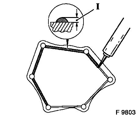
Important: The application of
silicone sealing compound, installation of timing case cover and
tightening to torque must be performed within 10 minutes!
|
| 147. |
Install timing case cover
Note: Apply an approx.
2 mm (Dimension I) thick bead of silicone sealing compound to
timing case cover
| • |
6 fastening bolts
| – |
Tightening torque 6 Nm / 4.5 lbf.
ft.
|
|
|
|
|
| 148. |
Install right engine bracket
| • |
3 fastening bolts
| – |
Tightening torque 55 Nm / 41 lbf.
ft.
|
|
|
| 149. |
Install compressor main bracket
| • |
2 fastening bolts
| – |
Tightening torque 35 Nm / 26 lbf.
ft.
|
|
|
| 150. |
Install compressor
| • |
3 fastening bolts
| – |
Tightening torque 20 Nm / 15 lbf.
ft.
|
|
|
| 151. |
Install alternator
| • |
Position coolant hose bracket
|
| • |
2 fastening bolts and 2 fastening nuts
| – |
Tightening torque 35 Nm / 26 lbf.
ft.
|
|
|
| 152. |
Install ribbed V-belt tensioner
| • |
2 fastening bolts
| – |
Tightening torque (M8) 20 Nm / 15 lbf.
ft.
|
| – |
Tightening torque (M10) 42 Nm / 31 lbf.
ft.
|
|
|
| 153. |
Attach ribbed V-belt
Note: Note running
direction
| • |
Tension ribbed V-belt tensioner at hex lug (1) anti-clockwise
(arrow)
|
|
|
|
| 154. |
Attach wiring harness bracket for engine management
|
| 155. |
Install wiring harness for engine management
| • |
Connect wiring harness plug.
| – |
Oil pressure switch, intake pipe pressure sensor, crankshaft
pulse pickup, EGR valve, engine control unit, coolant temperature
sensor, dynamic oil level control sensor, oil temperature sensor,
compressor
|
|
| • |
Connect wiring harness plug for sheathed glow plugs
|
| • |
Attach 2 turbocharge control vacuum hoses
| – |
Vacuum reservoir, solenoid valve
|
|
|
| 156. |
Attach wiring trough
|
| 157. |
Attach upper charge air pipe
| • |
1 clamp
| – |
Tightening torque 3.5 Nm / 2.6 lbf
ft
|
|
| • |
2 fastening bolts
| – |
Tightening torque 3 Nm / 2 lbf.
ft.
|
|
|
| 158. |
Top up engine oil.
| • |
Observe specified engine oil quantity
Note: After installing
the engine, the engine oil level must be checked and corrected if
necessary
|
|
| 159. |
Remove engine from engine assembly stands KM-412-A
|
| 160. |
Install engine
| • |
For X 20 DTL, Y 20 DTL and Y 20 DTH up to MY 2003
|
| • |
For Y 20 DTH as of MY 2003 and Y 22 DTR
|
|
|